 +86 755 2794 4155
  sales@knownpcb.com
-
Shenzhen KNOWNPCB Technology Co., Ltd.
 +86 755 2794 4155
  sales@knownpcb.com

Have you noticed that now more and more of our lighting is using led lighting.What is LED? Compared to the traditional light bulbs, LEDs have lower power consumption, longer lifetime and higher energy efficiency. In the PCB industry,when we say LED PCB, it refers to the pcb used for LED lighting, if you are looking for a suitable LED PCB for your lighting system, this article may bring you something. WHAT ARE LEDS COMPOSED OF?LED is an initial light-emitting diode that produces light when an electric current passes through. LEDs typically have negative and positive electrodes, which generate light in the visible light region.The LEDS are glued to the PCB by soldering process and have electrical connections for lighting.Since light-emitting diodes dissipate a lot of heat when they are in use, when you are designing LED, the metal core is usually the best choice for LED PCB, it is because that it dissipates heat more faster. Among them, the metal material aluminum is the most widely used
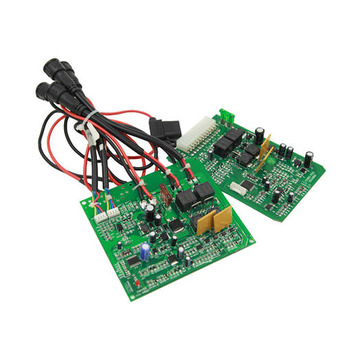
Due to cost and technical reasons, PCBs may encounter a large number of failure issues during production and application. In order to understand the cause of the failure and find a solution to the problem, it is necessary to conduct a failure analysis of the failure case. So, how to find the cause of PCB circuit board failure? Let the engineer share with you: The mechanism of PCB failure must follow basic principles and analysis processes. Firstly, it is necessary to determine the failure location and mode based on the failure phenomenon through information collection, functional testing, electrical performance testing, and simple visual inspection. Next, it is necessary to analyze the failure mechanism, which involves using various physical and chemical methods to analyze the mechanisms that cause PCB failure or defects, such as solder joints, contamination, mechanical damage, moisture stress, medium corrosion, fatigue damage, stress overload, and so on. Then there is the anal
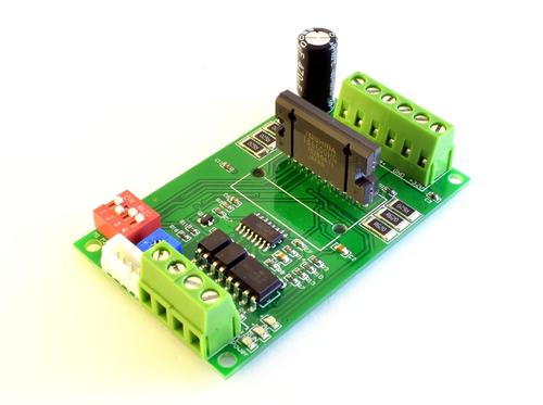
When designing PCB circuit board products, we often care about layout and wiring, which can easily overlook the additional PCB manufacturing costs in the design. Below, let's talk about the factors that affect the sampling price of PCB circuit boards in Shenzhen, in order to avoid increasing costs for customers. 1. Number of wiring layers. The price increases linearly with the number of layers, and the higher the number of layers, the more the price doubles. 2. Through hole. Normally, vias smaller than 0.25mm will be charged by the manufacturer. 3. Plug the hole in the disc. Unless there are strict requirements for signal and layout, try not to use it as it will increase costs. 4. Back drilling. Usually only used for high-speed signals such as backplanes. 5. Line width and line spacing. Usually less than 3.5 mils, additional fees will be charged. 6. Plate (high tg, high-frequency, unconventional) increases procurement cycle and production costs. 7. HDI and blind burial have
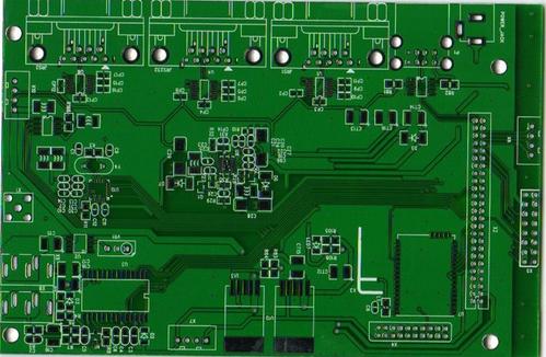
Wave soldering is a batch soldering process used for manufacturing PCB circuit boards, mainly used for soldering through hole components. So, what are the issues that need to be paid attention to in the wave soldering process of PCB circuit boards? 1. There is green oil inside the component hole, which leads to poor tin plating inside the hole. The green oil in the hole should not exceed 10% of the hole wall, and the number of holes in the internal green oil should not exceed 5%. 2. Insufficient coating thickness leads to poor tin plating in the hole. 3. The coating thickness on the component hole wall is insufficient, resulting in poor tin plating inside the hole. Usually, the thickness of the hole wall should be greater than 18 μ M. 4. The hole wall is too rough, resulting in poor tin plating or pseudo welding inside the hole. 5. The hole is damp, causing pseudo welding or bubbles. Sealing a PCB before drying or cooling, as well as leaving it for a long time after unpacking,
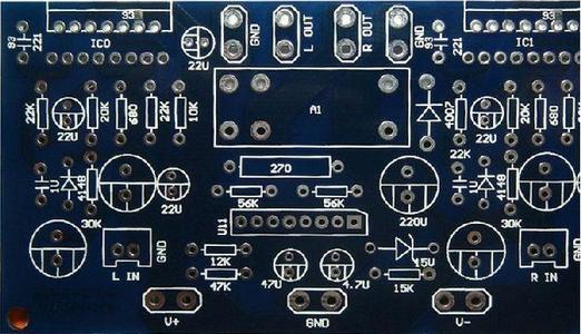
High frequency circuit wiring is a key and difficult issue in PCB circuit board design. Let Shenzhen PCB manufacturers share with you the high-frequency circuit wiring techniques for PCB design: 1. The less alternating layers of leads between pins in high-frequency circuit devices, the better The so-called "less alternating between lead layers is better" refers to the use of fewer vias (Via) during the component connection process. Reducing the number of vias can significantly improve speed and reduce the possibility of data errors. 2. The shorter the lead between the pins of high-frequency circuit devices, the better The radiation intensity of a signal is proportional to the length of the signal line, and the longer the high-frequency signal lead, the easier it is to couple to components close to it. 3. The less bent the leads between the pins of high-speed electronic devices, the better The lead wire for high-frequency circuit wiring should preferably be fully straight, and i
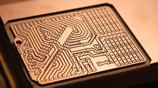
High frequency circuit wiring should pay attention to the "crosstalk" introduced by signal lines running parallel in close proximity, which refers to the coupling phenomenon between signal lines that are not directly connected. The parameters of the PCB board layer, the spacing between signal lines, the electrical characteristics of the driver and receiver ends, and the termination method of signal lines all have a certain impact on crosstalk. So, what are the measures for reducing high-frequency signal crosstalk in PCB wiring? 1. Inserting a ground wire or ground plane between two lines with severe crosstalk can provide isolation and reduce crosstalk; 2. If parallel distribution cannot be avoided, a large area of "ground" can be arranged on the opposite side of the parallel signal line to significantly reduce interference; 3. If the wiring space permits, the spacing between adjacent signal lines can be increased to reduce the parallel length of signal lines; 4. If parallel run
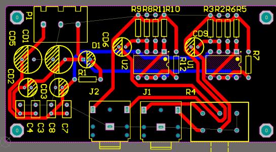
The EMC issue in PCB design is very important and plays a decisive role in the quality and performance stability of the next PCB circuit board. Below, let the engineer share with you: What factors are related to EMC issues in PCB design? 1. System design: When conducting system level EMC design, it is necessary to first determine the EMI interference source in order to systematically shield, filter, or use other methods to effectively eliminate EMI radiation sources. 2. Structural impact: If the radiation disturbance emission of non-metallic chassis exceeds the standard, measures such as conductive spraying, local shielding cover design, cable shielding treatment, and reasonable grounding treatment should be taken for the chassis. 3. Cable impact: Never use a cable shield as a return path for a signal. 4. The selection of components is related to: Taking varistors as an example: The main characteristic of varistors is their wide operating voltage range, which plays a role i
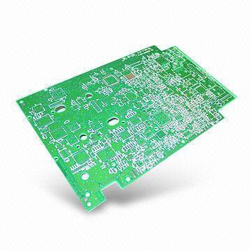
Aluminum substrate is a metal based copper clad plate with good heat dissipation function, commonly used for making LED lights. Next, let the Shenzhen PCB manufacturer provide you with a detailed explanation of the aluminum substrate production process specifications and difficulties. 1、 Aluminum substrate production process specification: 1. Aluminum substrates are often used in power devices, so copper foil is relatively thick. 2. The aluminum substrate should be protected with a protective film in advance, otherwise chemicals may corrode and cause damage to the appearance. 3. The milling cutters used for producing aluminum substrates have high hardness, and the milling cutter speed is at least two-thirds slower. 4. The processing of aluminum substrates must focus on adding alcohol to the gongs for heat dissipation. 2、 Difficulties in the production process of aluminum substrate: (1) Using mechanical processing of aluminum substrate, there should be no burrs on the edge of
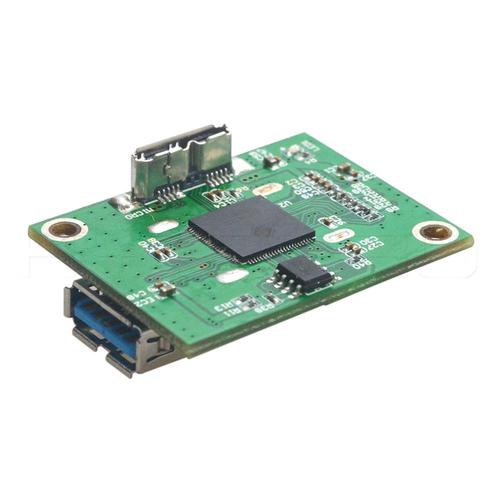
Circuit board design is a "slow work, meticulous work" job, where everyone has their own set of solutions. Below, let the engineer introduce to you the precautions for circuit board design? 1. Circuit board design should have a reasonable direction For example, input/output, AC/ DC, strong/weak signal, high/low frequency, high/low voltage, etc. Their directions should be linear (or separate) and cannot merge with each other. Its purpose is to prevent mutual interference. 2. Choose the appropriate contact position in circuit board design Usually, some commonality is required, such as the multiple grounding wires of the forward amplifier should converge and then be connected to the main line. In fact, due to various limitations, it is difficult to fully achieve this, but this principle should be followed as much as possible. 3. Circuit board design should correctly arrange capacitors Usually only a few power filters/decoupling capacitors are drawn, but it is not indicated where
Inquiry Now

