 +86 755 2794 4155
  sales@knownpcb.com
-
Shenzhen KNOWNPCB Technology Co., Ltd.
 +86 755 2794 4155
  sales@knownpcb.com

Have you noticed that now more and more of our lighting is using led lighting.What is LED? Compared to the traditional light bulbs, LEDs have lower power consumption, longer lifetime and higher energy efficiency. In the PCB industry,when we say LED PCB, it refers to the pcb used for LED lighting, if you are looking for a suitable LED PCB for your lighting system, this article may bring you something. WHAT ARE LEDS COMPOSED OF?LED is an initial light-emitting diode that produces light when an electric current passes through. LEDs typically have negative and positive electrodes, which generate light in the visible light region.The LEDS are glued to the PCB by soldering process and have electrical connections for lighting.Since light-emitting diodes dissipate a lot of heat when they are in use, when you are designing LED, the metal core is usually the best choice for LED PCB, it is because that it dissipates heat more faster. Among them, the metal material aluminum is the most widely used
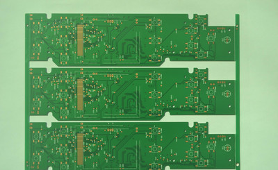
For information on how to best apply DFA, see Why DFA is important for your PCB design and development process. For certain designs, in addition to normal functional testing performed during the prototype phase, testing may also be required. Moreover, this additional test may require you to expand the design to accommodate test equipment, such as adding test points or building test equipment for ROSE testing as needed. For more information about DFT, see Design for Testability (DFT): Do you really need it? For DFR (which should also be included in DFX), the goal is to make design decisions that, once installed and operational, will help improve the reliability performance of the circuit board. These choices will affect the manufacturing, assembly, and components used in your circuit board, as described in the following section.
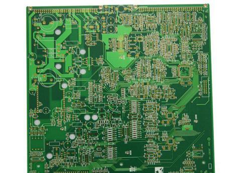
Multilayer circuit board: refers to a printed circuit board with three or more layers of conductive graphics and insulating materials between them, which are laminated and separated, and the conductive graphics between them are interconnected as required. Multilayer circuit boards are a product of the development of electronic information technology towards high speed, multifunctional, large capacity, small volume, thinness, and lightweight. Single sided circuit board: On the most basic PCB, parts are concentrated on one side and wires are concentrated on the other side. Because wires only appear on one side, this type of PCB is called a single sided circuit board. Single panel production is usually simple and cost-effective, but the disadvantage is that it cannot be applied to products that are too complex. Double-sided circuit board: It is an extension of a single panel. When single-layer wiring cannot meet the needs of electronic products, a double-sided board should be used.
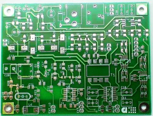
The working principle of a circuit board is to use board based insulation materials to isolate the surface copper foil conductive layer, allowing current to flow along a pre designed route in various components to complete functions such as work, amplification, attenuation, modulation, demodulation, encoding, etc. The circuit board mainly consists of solder pads, vias, mounting holes, wires, components, connectors, thin film circuit SMT patches for Watford circuit boards, SMT patches for thin film circuit SMT patches, fillers, electrical boundaries, etc. The main functions of each component are as follows: Solder pad: A metal hole used for soldering component pins. Through hole: There are metal through holes and non-metal through holes, where metal through holes are used to connect component pins between layers. Installation hole: used to fix the circuit board. Wire: An electrical network copper film used to connect component pins. Connector: A component used for connecting c
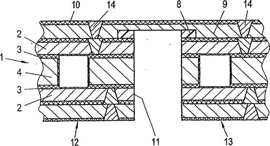
For end users, the ability of your circuit board to perform its expected functions is a basic requirement. More importantly, they remain consistent throughout their expected lifespan. When your design process targets reliability, it is best to achieve this level of performance, including the following. After PCBA is put into operation, its performance will be determined after development and production. The goal of this stage is to ensure that the circuit board always performs its functions or makes it reliable throughout its entire lifecycle. The failure rate of all produced circuit boards is 0%, which is a high standard because circuit boards may encounter unforeseeable situations that are not considered in the design or manufacturing process. Therefore, we should revise our goal to minimize failure rates and maximize service life. Although performance is a post production indicator, it is determined by the measures taken during the development process. An effective PCBA develo

For information on how to best apply DFA, see Why DFA is important for your PCB design and development process. For certain designs, in addition to normal functional testing performed during the prototype phase, testing may also be required. Moreover, this additional test may require you to expand the design to accommodate test equipment, such as adding test points or building test equipment for ROSE testing as needed. For more information about DFT, see Design for Testability (DFT): Do you really need it? For DFR (which should also be included in DFX), the goal is to make design decisions that, once installed and operational, will help improve the reliability performance of the circuit board. These choices will affect the manufacturing, assembly, and components used in your circuit board, as described in the following section.
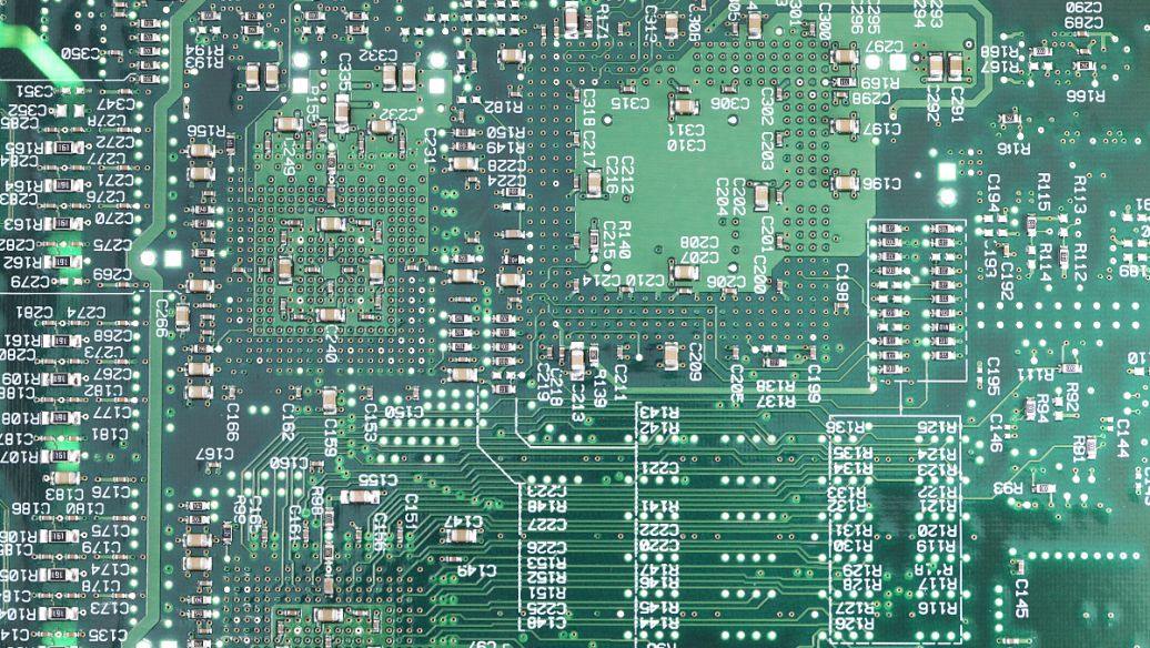
For end users, the ability of your circuit board to perform its expected functions is a basic requirement. More importantly, they remain consistent throughout their expected lifespan. When your design process targets reliability, it is best to achieve this level of performance, including the following. After PCBA is put into operation, its performance will be determined after development and production. The goal of this stage is to ensure that the circuit board always performs its functions or makes it reliable throughout its entire lifecycle. The failure rate of all produced circuit boards is 0%, which is a high standard because circuit boards may encounter unforeseeable situations that are not considered in the design or manufacturing process. Therefore, we should revise our goal to minimize failure rates and maximize service life. Although performance is a post production indicator, it is determined by the measures taken during the development process. An effective PCBA develo
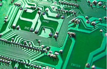
The working principle of a circuit board is to use board based insulation materials to isolate the surface copper foil conductive layer, allowing current to flow along a pre designed route in various components to complete functions such as work, amplification, attenuation, modulation, demodulation, encoding, etc. The circuit board mainly consists of solder pads, vias, mounting holes, wires, components, connectors, thin film circuit SMT patches for Watford circuit boards, SMT patches for thin film circuit SMT patches, fillers, electrical boundaries, etc. The main functions of each component are as follows: Solder pad: A metal hole used for soldering component pins. Through hole: There are metal through holes and non-metal through holes, where metal through holes are used to connect component pins between layers. Installation hole: used to fix the circuit board. Wire: An electrical network copper film used to connect component pins. Connector: A component used for connecting c
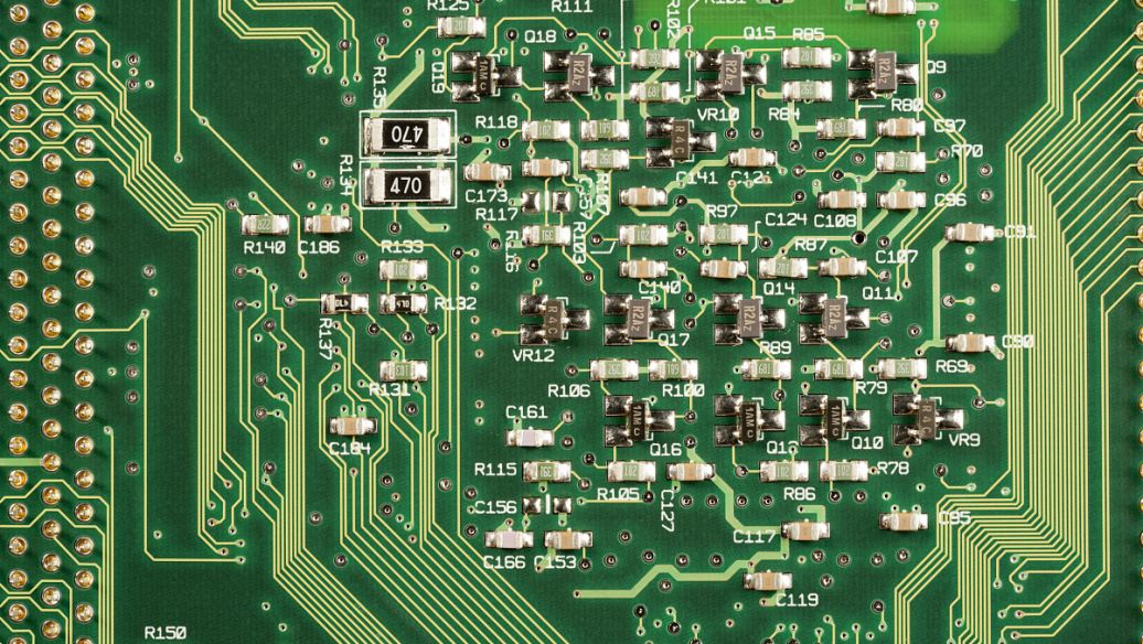
Multilayer circuit board: refers to a printed circuit board with three or more layers of conductive graphics and insulating materials between them, which are laminated and separated, and the conductive graphics between them are interconnected as required. Multilayer circuit boards are a product of the development of electronic information technology towards high speed, multifunctional, large capacity, small volume, thinness, and lightweight. Single sided circuit board: On the most basic PCB, parts are concentrated on one side and wires are concentrated on the other side. Because wires only appear on one side, this type of PCB is called a single sided circuit board. Single panel production is usually simple and cost-effective, but the disadvantage is that it cannot be applied to products that are too complex. Double-sided circuit board: It is an extension of a single panel. When single-layer wiring cannot meet the needs of electronic products, a double-sided board should be used. Bo
Inquiry Now

