 +86 755 2794 4155
  sales@knownpcb.com
-
Shenzhen KNOWNPCB Technology Co., Ltd.
 +86 755 2794 4155
  sales@knownpcb.com

Have you noticed that now more and more of our lighting is using led lighting.What is LED? Compared to the traditional light bulbs, LEDs have lower power consumption, longer lifetime and higher energy efficiency. In the PCB industry,when we say LED PCB, it refers to the pcb used for LED lighting, if you are looking for a suitable LED PCB for your lighting system, this article may bring you something. WHAT ARE LEDS COMPOSED OF?LED is an initial light-emitting diode that produces light when an electric current passes through. LEDs typically have negative and positive electrodes, which generate light in the visible light region.The LEDS are glued to the PCB by soldering process and have electrical connections for lighting.Since light-emitting diodes dissipate a lot of heat when they are in use, when you are designing LED, the metal core is usually the best choice for LED PCB, it is because that it dissipates heat more faster. Among them, the metal material aluminum is the most widely used
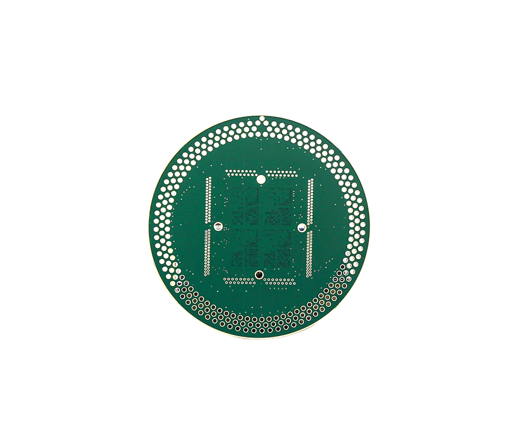
The equipment used for curing plastic melt ink is not suitable for curing water-based ink. Except for discharge ink, other water-based inks contain chemical cross-linking agents. Only when water-based inks are sufficiently dried can they ensure the washing fastness of printed images. Some printing factories choose air drying for the solidification of water-based ink, while others make the printed matter come into direct contact with a hot platform before the ink dries, causing the moisture to evaporate, and then place the printed matter in an oven. Before coating the paper, a drying device should be used to remove moisture from the paper, which is also suitable for removing moisture from water-based inks. Perhaps the most reasonable way to remove moisture is to avoid adding water to the printing process. Therefore, if it is possible to print transparency on light or white fabrics Ink, which means using fine screen printing transparent ink, will have very little moisture.
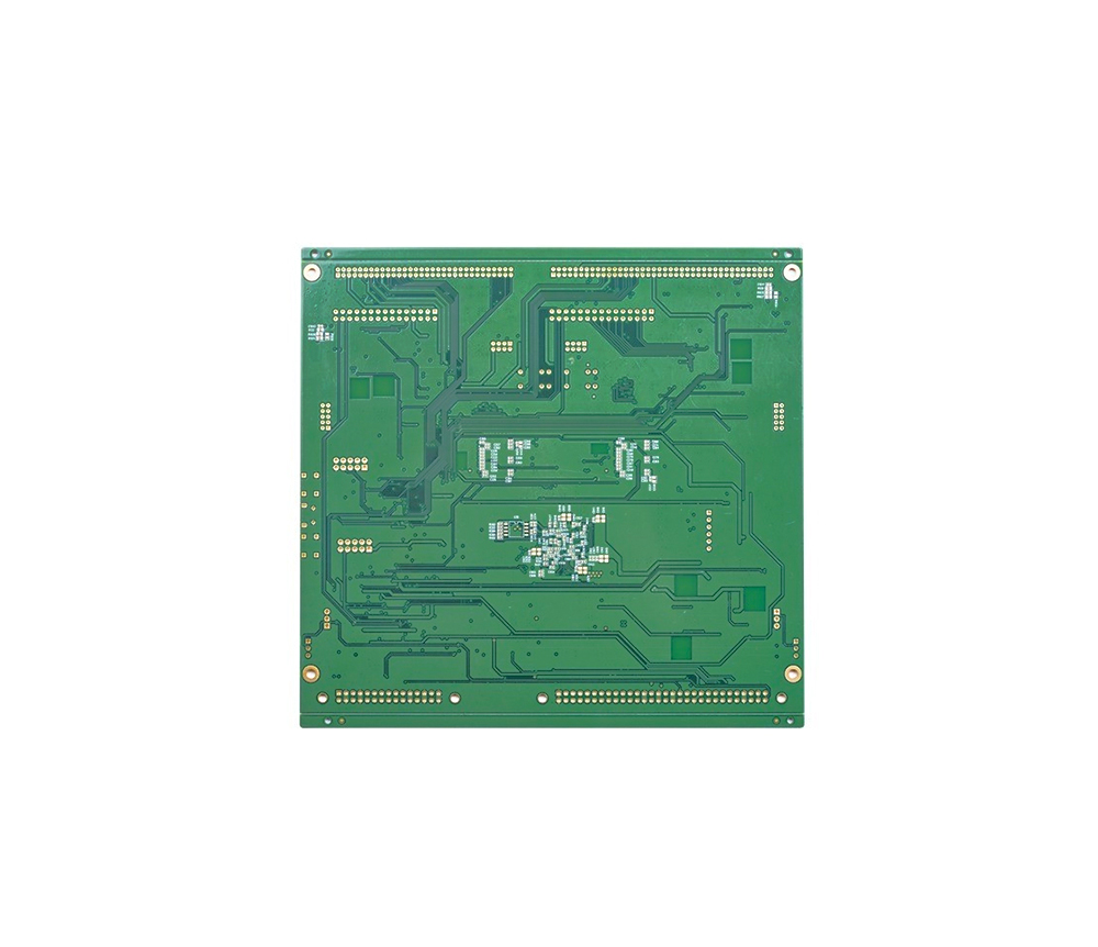
(1) One point grounding Concentrate several grounding points of the same level unit circuit as much as possible to avoid the AC signal from other circuits from entering the same level or from the AC signal in the same level from entering other circuits. Suitable for low-frequency circuits with a working frequency of less than 1MHz. If a single point grounding is used when the working frequency is between 1-1OMHz, the length of the ground wire should not exceed 1/20 of the wavelength. In short, single point grounding is the basic principle for eliminating common impedance interference of the ground wire. (2) Multiple grounding points nearby There are a large number of common ground wires distributed at the edges of the PCB and present a semi closed circuit (anti magnetic field interference). All levels of circuits are grounded nearby to prevent the ground wires from being too long. Suitable for high-frequency circuits with signal operating frequencies greater than lOMHz. (3) Groun
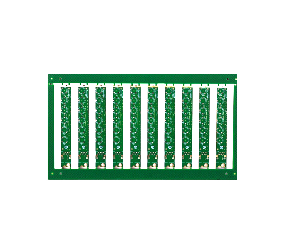
Mechanical characteristics of PCB through holes When the PCB through-hole is large, our wiring space will be very small. Obviously, we want to use small PCB through-holes, but how small is appropriate? Even if the PCB plate making via is already very small and the PCB plate making via is smaller, more lines can be laid on the PCB to improve the wiring density. For products with limited product size, designers have to make the PCB through holes on the board smaller and smaller. The smaller the PCB through hole, the smaller the parasitic capacitance. This means that the smaller the PCB through hole, the better it will work in high-speed situations. In the fastest PCB design, small PCB through holes are mandatory. Of course, the cost of generating small PCB through holes is higher. In engineering design, it is inevitable that the higher the performance, the higher the cost, and PCB through holes are no exception. At present, we have three principles for PCB through holes: Small PCB th
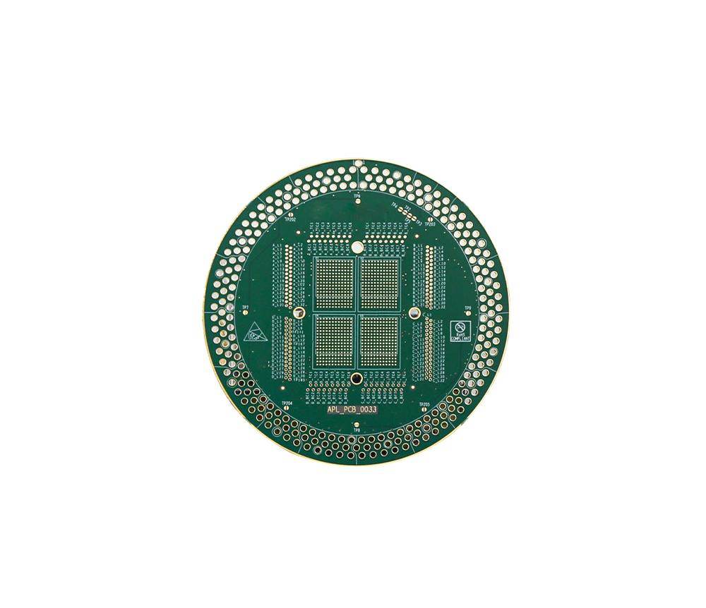
PCB process PK: tin spraying vs gold plating vs gold deposition Gold plate and gilded plate are commonly used processes in the production of circuit boards nowadays, and many people are unable to correctly distinguish the differences between the two. Some even believe that there is no difference between the two, but in fact, they are not. Usually, when people choose gold plating, what is gold plating? When we refer to whole plate gold plating, we generally refer to "electroplated gold", "electroplated nickel gold plate", "electrolytic gold", "electroplated gold", "electroplated nickel gold plate". There is a distinction between soft gold and hard gold (usually hard gold is used for gold fingers), and the principle is to dissolve nickel and gold (commonly known as gold salt) in chemical solution, Immerse the circuit board in an electroplating cylinder and apply current to generate a nickel gold coating on the copper foil surface of the circuit board. Electroplated nickel gold is wide
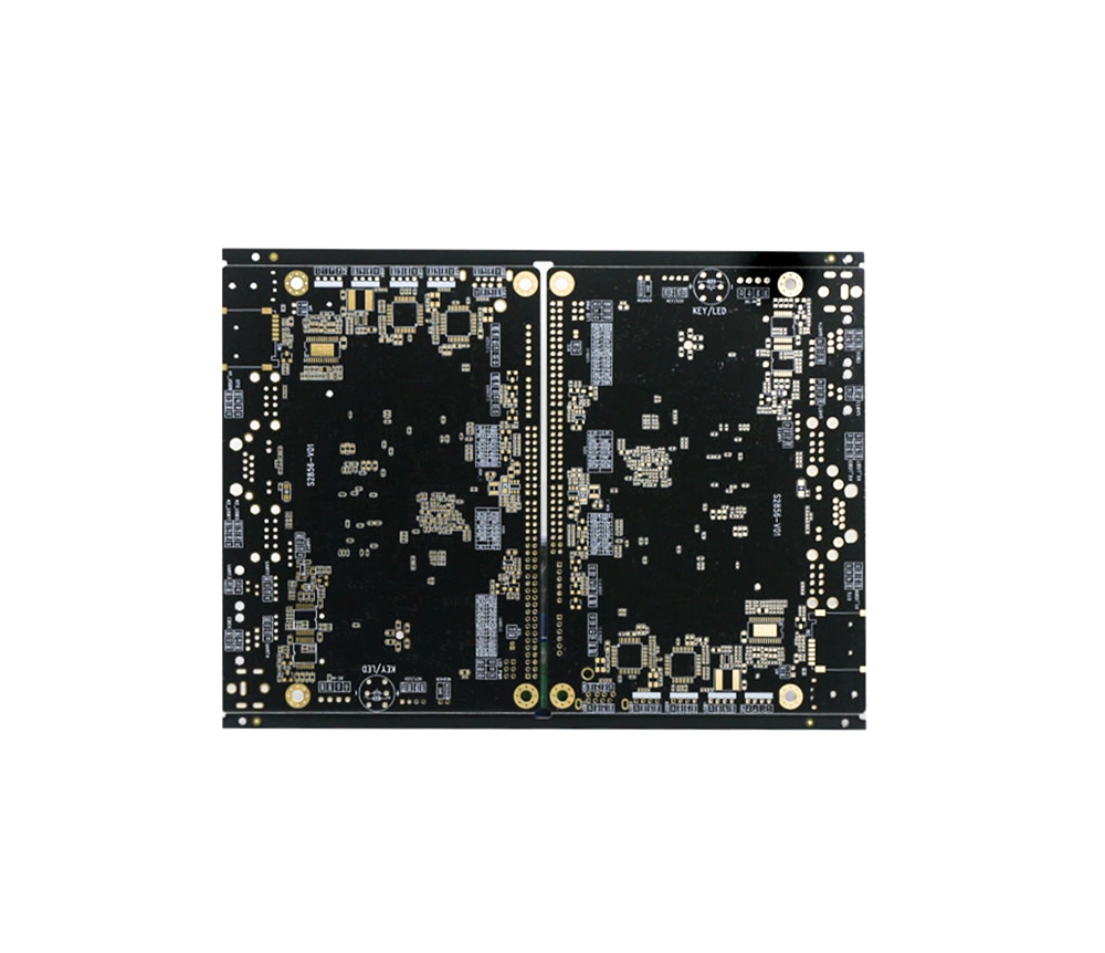
The difference between PCB tin spraying and PCB tin plating The cost of PCB solder board is relatively low because it only sprays tin on the PCB on the solder pad, while tin plating includes tin on the circuit as well. PCB tin plating, as the name suggests, is the process of depositing a thin layer of tin at the PCB pad location using chemical methods, usually ranging from 10 to 30 microns. The main purpose is to prevent oxidation and better fuse SMT tin. In fact, the same purpose as gold plating and OSP requires additional tin plating during SMT. PCB tin spraying refers to the physical method of spraying a layer of tin, usually ranging from 50 to 150 microns in thickness, which is relatively thick. Do not apply tin during SMT, just melt the tin onto the component. The composition of the two types of tin must be different. PCB based tin uses a salt of tin, and the mixture is an acidic solution containing tin. But PCB tin spraying generally uses tin alloys, which are generally divide
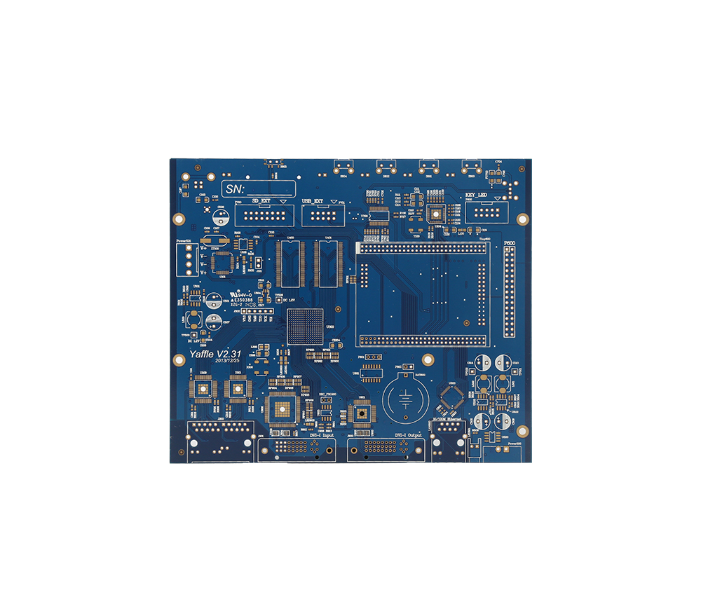
Reasons and Preventive Measures for Poor PCB Surface Mount Welding 1、 Poor wetting Poor wetting refers to the welding process where the solder and PCB substrate welding area, after being soaked, do not generate metal to metal reactions, resulting in missed or missing solder faults. The reason for this is mostly due to the surface contamination of the welding area, or the adhesion of solder resist, or the formation of a metal compound layer on the surface of the joint, such as the presence of sulfides on the surface of silver and oxides on the surface of tin, which can cause poor wetting. In addition, when the residual aluminum, zinc, cadmium, etc. in the solder exceeds 0.005%, the wetting effect of the solder reduces the activity and can also lead to poor wetting. In wave soldering, if there is gas present on the surface of the PCB substrate, this fault is also prone to occur. Therefore, in addition to implementing appropriate welding processes, anti fouling measures should be take
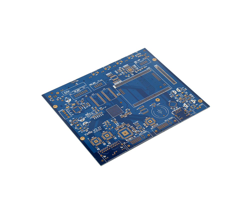
The automotive electronics market is the third largest application field for PCBs after computers and communication. With the gradual evolution and development of automobiles from traditional mechanical products to intelligent, information-based, mechatronics high-tech products, electronic technology has been widely used in automobiles, and electronic products have been used without exception in engine systems, chassis systems, safety systems, information systems, vehicle Internal environment systems, etc. The automotive market has clearly become another highlight of the electronic consumer market, and the development of automotive electronics has naturally driven the development of automotive PCBs. Among the key application objects of PCB today, automotive PCBs occupy an important position. However, due to the special working environment, safety, and high current requirements of automobiles, they have high requirements for the reliability and environmental adaptability of PCBs, and
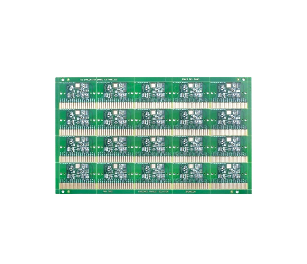
The ion transport caused by electrostatic force in electroplating solution is called ion migration. The migration rate is expressed as follows: u=zeoE/6 π r η Yes. Where u is the ion migration rate, z is the charge number of the ion, and eo is the charge amount of one electron (i.e. 1.61019CE is the potential, r is the radius of the hydrated ion η Is the viscosity of the electroplating solution. According to the calculation of the equation, it can be seen that under the action of the electric field. The greater the decrease in potential E, the smaller the viscosity of the electroplating solution, and the faster the rate of ion migration. When electroplating, according to the theory of electrodeposition. The PCB located on the cathode is a non ideal polarized electrode. Copper ions adsorbed on the surface of the cathode obtain electrons and are reduced to copper atoms, resulting in a decrease in the concentration of copper ions near the cathode. Therefore, a copper ion concentratio
Inquiry Now

