 +86 755 2794 4155
  sales@knownpcb.com
-
Shenzhen KNOWNPCB Technology Co., Ltd.
 +86 755 2794 4155
  sales@knownpcb.com

Have you noticed that now more and more of our lighting is using led lighting.What is LED? Compared to the traditional light bulbs, LEDs have lower power consumption, longer lifetime and higher energy efficiency. In the PCB industry,when we say LED PCB, it refers to the pcb used for LED lighting, if you are looking for a suitable LED PCB for your lighting system, this article may bring you something. WHAT ARE LEDS COMPOSED OF?LED is an initial light-emitting diode that produces light when an electric current passes through. LEDs typically have negative and positive electrodes, which generate light in the visible light region.The LEDS are glued to the PCB by soldering process and have electrical connections for lighting.Since light-emitting diodes dissipate a lot of heat when they are in use, when you are designing LED, the metal core is usually the best choice for LED PCB, it is because that it dissipates heat more faster. Among them, the metal material aluminum is the most widely used
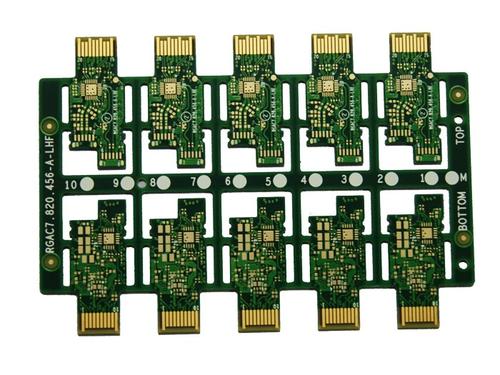
① Dielectric constant: Dk needs to be small and stable. Generally, the smaller Dk, the faster the signal transmission speed, which is inversely proportional to the square root of the dielectric constant of the substrate. The larger Dk, the more likely it is to cause signal transmission delay. ② Dielectric loss: At the same time, the smaller the Dk, the better the signal transmission quality, and the smaller the dielectric loss, the smaller the signal loss. ③ The thermal expansion coefficient of copper foil should be consistent as much as possible, with low water absorption, other heat resistance, chemical resistance, impact strength, peel strength, and other aspects that must be well protected. Normally, high-frequency boards are defined as above 1GHz. Currently, most of the high-frequency circuit board substrates produced are fluorine based dielectric substrates, such as Teflon, which are mostly used for frequencies above 5GHz. Other FR4 substrates are used between 1GHz and 10G
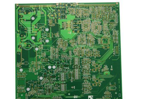
① Benefits: Both high-frequency circuits and low-frequency power supply circuits have voltage gain and output power harvesting effects. Resonant differential amplification circuits refer to the resonant frequency f0, and for fiber optic broadband differential amplification circuits, they refer to a frequency range. ② Pass band: The concept is quite different from that of low-frequency power circuit boards. For resonant differential amplification circuits, most of them are the values between the two corresponding frequencies when the normalized vibration amplitude of the resonance frequency f0 decreases to 0.707; For fiber optic broadband amplification circuits, it refers to the corresponding meaning relative to a certain frequency. ③ Selectivity: Selectivity is mainly aimed at resonant amplification circuits, which characterizes the selection of useful signals and the suppression ability of useless signals in the circuit. It is usually measured using rectangular coefficient and s
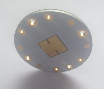
At present, the common colors of PCB circuit boards in the market are green, black, blue, yellow, purple, red, and brown, and recently white and pink PCBs have also appeared. So, why do PCB circuit boards have different colors? Have you noticed that most circuit boards are green, while other colors are rare? Why is this? Next, the editor of the circuit board manufacturer will spread a wave of knowledge about circuit boards to everyone~ In the production of PCB boards, the final surface of the copper layer is smooth and unprotected, whether it is additive or subtractive. Although the chemical properties of copper are not as good as those of aluminum, iron, and magnesium, pure copper is prone to oxidation under water conditions when in contact with oxygen. However, the thickness of the copper layer in PCB circuit boards is very thin, and the oxidized copper can become a poor conductor of electricity, greatly damaging the electrical performance of the entire PCB. In order to preven
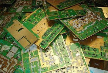
PCB, also known as printed circuit board, is a provider of electrical connections for electronic components, and its design mainly involves layout design; The main advantage of using circuit boards is that they greatly reduce wiring and assembly errors, improve automation levels and production labor rates. The existence of PCBs has a history of over 100 years. PCBA: PCBA is the entire process of SMT loading on an empty PCB board, followed by DIP plugins. The differences between them include: 1. Different functions PCBs can make programs that cannot run independently a unit that runs independently. The excellent circuit design of PCBA can achieve good circuit performance and heat dissipation performance. 2. Essentially different PCBA generally refers to a processing process, which can also be said to be a finished circuit board, that is, a PCB that is completed after processing.
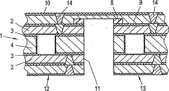
The so-called blind hole circuit board refers to non drilled holes. The difference between blind holes and through holes is that through holes are holes drilled through each layer. When making blind hole boards, drilling is done before pressing, while through holes are drilled after pressing. What basic knowledge do you need to know in the manufacturing of blind hole PCB circuit boards Blind hole PCB circuit board ① Drill tape: Select through holes as unit reference holes. Each blind hole drill tape needs to select a hole and identify its corresponding unit reference hole coordinates, and note which drill tape corresponds to which layers. When the laser hole is sleeved with the inner buried hole, even if the holes of the two drill tapes are in the same position, it is necessary to confirm with the customer. Move the position of the laser hole to ensure electrical connection, and do not handle it arbitrarily based on experience. ② Process holes: The inner layer of ordinary multi-
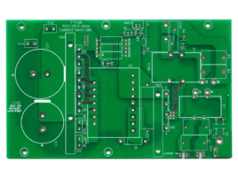
1. Heat dissipation through the circuit board itself: Currently, the most widely used substrates for printed circuit boards are copper clad/epoxy glass cloth substrates, phenolic resin glass cloth substrates, paper based copper clad substrates, etc. Although these substrates have good electrical and processing properties, their heat dissipation is poor, and they are still not competent for some products with high current requirements. With the continuous updating of precision products, The volume of the PCB board is also decreasing, but the precision is constantly increasing. If only the surface is used for heat dissipation, it is far from enough. The best way to solve this problem is to improve the heat dissipation ability of the PCB board itself, which is directly in contact with the heating element, and transmit heat out through the circuit board itself. 2. When designing a PCB circuit board, a reasonable circuit layout can also achieve heat dissipation. Apart from the poor the
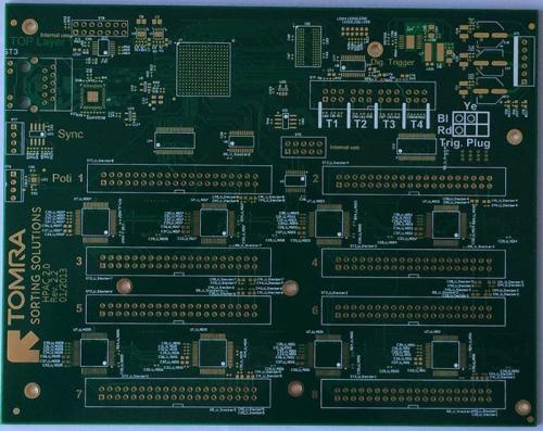
The color of the solder mask layer mainly depends on the color of the solder mask ink. Green ink is currently the most widely used and the cheapest in the market. In fact, the soldering ink on the market is not only limited to green, but also has various colors such as red, blue, purple, black, and yellow. However, green is the most common, and the main reason is that using green soldering ink has the following advantages: it is easy for optical positioning correction. The production process of the circuit board itself includes the STM welding process, which requires soldering and final AOI verification. These processes require optical positioning calibration, and the green background color has a better recognition effect on the instrument. The visual effect is better in the yellow light room. The entire PCB board product undergoes processes such as board making and SMT during the production process. Usually, when circuit boards are used in the production and processing of electroni
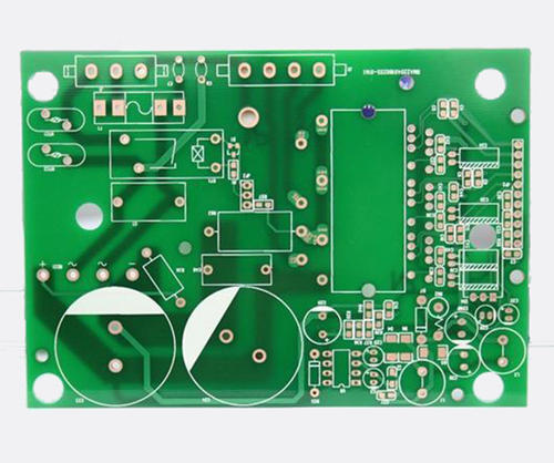
FPC flexible circuit board is a highly reliable and excellent flexible printed circuit board made of PI polyimide or polyester film as the substrate. It has the characteristics of high wiring density, light weight, thin thickness, and good bending performance. PI, as a special engineering material, has been widely used in fields such as aviation, aerospace, microelectronics, nanomaterials, liquid crystals, separation membranes, lasers, etc. The long-term use temperature is between -200 ℃ and 426 ℃. PI polyimide is common in FPC flexible circuit boards, as it exists in substrates, covering films, and even reinforcement. Some people may be confused about this, so today let's discuss the difference between them? The functional differences between the substrate, covering film, and PI reinforcement of FPC flexible circuit boards are as follows: 1 PI substrate: For FPC flexible circuit board substrates, there are two types: adhesive substrate and non adhesive substrate. PI polyimide is
Inquiry Now

