 +86 755 2794 4155
  sales@knownpcb.com
-
Shenzhen KNOWNPCB Technology Co., Ltd.
 +86 755 2794 4155
  sales@knownpcb.com
 2024-08-21
 300
300

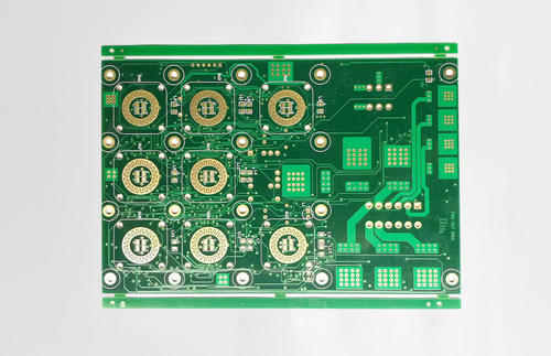
Printed circuit board (PCB) is almost present in every electronic device. If there are electronic components in a certain device, they are also embedded on PCBs of different sizes. In addition to fixing various small parts, the main function of PCB is to provide electrical connections between the various components on top. As electronic devices become increasingly complex and require more and more parts, the circuits and components on the PCB are also becoming denser. A standard PCB looks like this. Bare board (without components on top) is also commonly referred to as "Printed Wiring Board (PWB)".
The substrate of the board itself is made of insulated and non bendable materials. The small circuit material visible on the surface is copper foil. Originally, the copper foil covered the entire board, but during the manufacturing process, some parts were etched away, leaving behind a network of small circuits. These circuits are called conductor patterns or wiring, and are used to provide circuit connections for components on the PCB.
To fix the parts on the PCB, we solder their pins directly onto the wiring. On the most basic PCB (single panel), parts are concentrated on one side, while wires are concentrated on the other side. In this way, we need to drill holes on the board so that the pins can pass through the board to the other side, so the pins of the parts are welded to the other side. Therefore, the front and back sides of the PCB are respectively referred to as the component side and the solder side.
If there are certain components on the PCB that need to be removed or reinstalled after production, sockets will be used for the installation of these components. Due to the fact that the socket is directly soldered onto the board, the parts can be disassembled and assembled at will. The following is the ZIF (Zero Insertion Force) socket, which allows components (referring to CPUs) to be easily plugged into the socket or removed. The fixing rod next to the socket can be fixed after you insert the part.
If we want to connect two PCBs to each other, we usually use edge connectors commonly known as "golden fingers". The golden finger contains many exposed copper pads, which are actually part of the PCB wiring. Usually, when connecting, we insert the gold finger on one PCB into a suitable slot on the other PCB (usually called an expansion slot). In computers, graphics cards, sound cards, or other similar interface cards are connected to the motherboard through gold fingers.

Or call +86 755 2794 4155
Inquiry Now

