 +86 755 2794 4155
  sales@knownpcb.com
-
Shenzhen KNOWNPCB Technology Co., Ltd.
 +86 755 2794 4155
  sales@knownpcb.com
 2024-11-21
 646
646

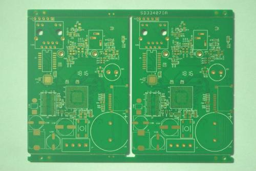
Mixed - signal PCBs are a complex and crucial part of modern electronic design. These PCBs handle both analog and digital signals simultaneously, presenting unique challenges and opportunities.
In the design of mixed - signal PCBs, one of the primary concerns is signal isolation. Since analog signals are sensitive to noise and interference from digital signals, proper separation techniques are essential. This often involves using physical barriers such as ground planes or isolation trenches. Ground planes act as a reference for signals and help in reducing electromagnetic interference. Isolation trenches, on the other hand, are created by etching away the substrate material between different signal areas to prevent crosstalk. For example, in a mixed - signal PCB for an audio - processing device, the analog audio signals must be kept free from the digital control signals to maintain high - quality sound reproduction.
Component placement also plays a vital role. Analog components, like operational amplifiers and voltage regulators, are usually placed in areas with minimal digital noise. Digital components, such as microcontrollers and digital signal processors, are grouped together. However, careful routing is still required to ensure that the digital signals do not interfere with the analog components. The power supply for analog and digital parts is often separated to avoid noise coupling through the power lines. Special attention is given to the power - decoupling capacitors near sensitive analog components to smooth out any voltage fluctuations.
Routing of the signals is another critical aspect. Analog signal paths are kept short and direct to minimize signal loss and interference. Digital signal routing follows different rules based on the speed and complexity of the signals. High - speed digital signals require controlled impedance routing to prevent signal reflections. In mixed - signal PCBs, the interaction between these different types of routing needs to be carefully managed. For instance, when a digital signal crosses an analog signal path, it should do so at a right angle to minimize crosstalk.
Testing and verification of mixed - signal PCBs are more complex than those for single - signal type PCBs. Both analog and digital signals need to be tested for proper functionality. Specialized test equipment, such as spectrum analyzers for analog signals and logic analyzers for digital signals, are used. The performance of the PCB in terms of signal - to - noise ratio, gain accuracy (for analog signals), and bit error rate (for digital signals) is carefully evaluated to ensure that the mixed - signal PCB meets the design requirements.

Or call +86 755 2794 4155
Inquiry Now

