 +86 755 2794 4155
  sales@knownpcb.com
-
Shenzhen KNOWNPCB Technology Co., Ltd.
 +86 755 2794 4155
  sales@knownpcb.com
 2023-09-13
 150
150

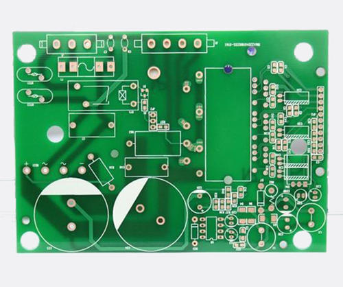
In PCB design, wiring is an important step in completing product design, and it can be said that the previous preparation work was done for it. PCB wiring includes single-sided wiring, double-sided wiring, and multi-layer wiring. There are also two types of wiring methods: automatic wiring and interactive wiring. Today, let professional engineers explain in detail what PCB wiring rules and techniques are available for you?
1. Handling of power and ground wires
The interference caused by improper handling of power and ground wires can lead to a decrease in product performance, and sometimes even affect the success rate of the product. Therefore, the wiring of power and ground wires should be taken seriously, and the noise interference generated by the power and ground wires should be minimized to ensure the quality of the product. The specific approach is as follows:
(1) Add a coupling capacitor between the power supply and ground wire.
(2)
Try to widen the width of the power and ground wires as much as possible. The relationship between them is ground wire>power wire>signal wire. Usually, the signal wire width is 0.2-0.3mm, with the longest and narrowest width reaching 0.05-0.07mm and the power wire being 1.2-2.5mm.
(3) For digital circuit PCBs, a wide ground wire can be used to form a circuit.
(4) Make it into a multi-layer board, with power and ground wires occupying one layer each.
2. Common ground processing of digital and analog circuits
Many PCBs are not single functional circuits, but are composed of a mixture of digital and analog circuits. Therefore, when wiring, it is necessary to consider the issue of mutual interference between them, especially the noise interference on the ground wire.
The frequency of digital circuits is high, while the sensitivity of analog circuits is strong. For ground wires, a PCB only has one node to the outside world, so it is necessary to handle the problem of common ground between digital and analog components inside the PCB; However, the digital ground and analog ground inside the board are actually separated, only at the interface between the PCB and the outside world (such as a plug), where there is only one connection point between the digital ground and analog ground.

Or call +86 755 2794 4155
Inquiry Now

